
Games
Repairing Robotron
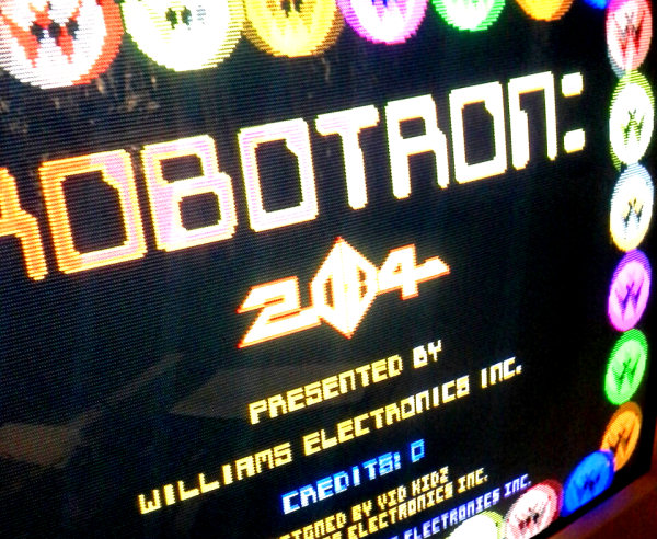
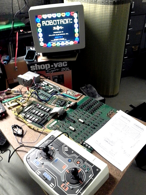
As far as I’m concerned the best game ever made is Robotron, an 8-bit arcade game from 1982. Two joysticks, no buttons, and more than a hundred baddies on a single screen. It’s intense and it’s awesome.
My PCB has been through a lot, I’ve had it for more than 15 years, and of course the game was released more than thirty years ago. When I first got it I had whipped up a JAMMA interface board so I could play it on any modern arcade cabinet, and this required a fairly large custom wire harness, a video sync inverter chip, a volume control knob etc. Anyway, last time I played it, it worked fine.
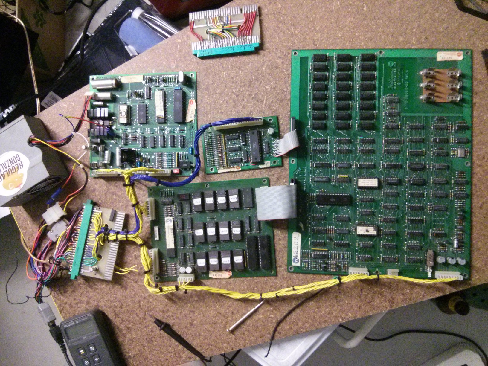
Click for larger image
When I fired it up this time, however, it wasn’t working.
1. No Sound
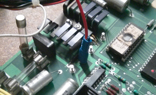
First up, Robotron needs -12V for the audio circuit. Originally I had simply wired -5V to the -12V input because that’s what the JAMMA harness supplied, but the power connector I was using for this configuration only supplied +5V and +12V. So I added -5V and the audio came to life.
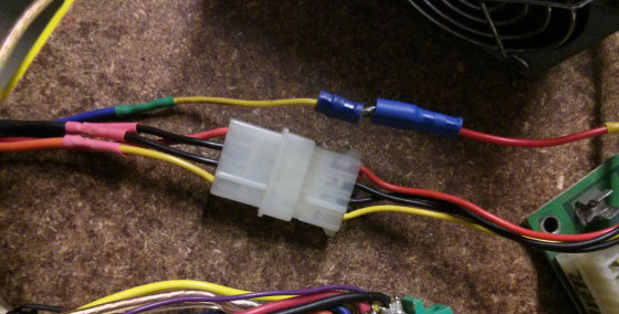
Since I was using a PC power supply, there was a standard PC HDD power connector already wired up, so that’s what I used for powering my JAMMA rig. Almost all my games used only 12V and 5V, so I never missed the negative voltages until I started hooking up the older games as well. In the image above you can see the power connector and the new -5V wire above it.
2. Bad Inputs
I plugged in my recently re-built Robotron stick, and realized pretty quickly that the DOWN direction was stuck. The player could not go up, and always ended up at the bottom of the screen in short order. It’s sort of like playing Robotron: Gravity Edition, and if that sounds like fun please allow me to assure you it is not fun.
I pulled apart the stick and double-checked my wiring to no avail. Robotron’s self-test revealed that the P1 and P2 DOWN input was always active (which definitely ruled out my stick, because there were no inputs for P2 connected at all).
The first thing I did was check the wiring. There’s a 20-pin ribbon cable connecting the interface board to the main CPU board, and I had worked on it before, so guessed that perhaps it needed to be rebuilt. After crimping the appropriate connectors a few times I basically ruined them, and so I used a dremel and a screwdriver and soldering iron to cut and pry the old 20-pin PCB connector, and then directly solder 20 new wires. And since I had ruined the 20-pin connector on the CPU side and didn’t have a spare, I resorted to floppy-drive cable. It had 14 extra pins, but it’d do the job.
But of course it still didn’t work…
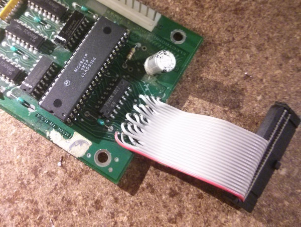
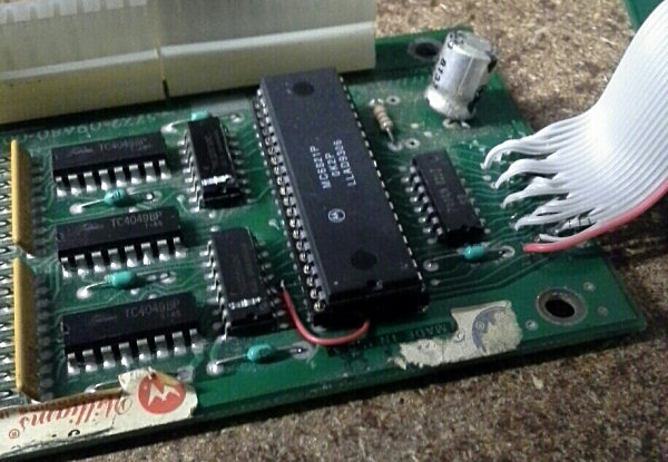
So I checked the schematic and traced the circuit and everything appeared fine, up to the PIA chip, the last step before the 20-pin cable connects to the CPU board.
Now, in Robotron, there are several PIA (Peripheral Interface Adaptor) chips which provide communications between several components and the CPU. The ROM board, controller input board and sound board all have their own PIA chips. So I ordered another PIA off ebay, along with a socket, and when it arrived I cut the old chip out and soldered a new one in. In doing so I realized someone had replaced the PIA once already…
And the new PIA didn’t solve the problem. I looked closer at the PCB, and there was a cut trace (somehow, I can’t imagine how, I honestly can’t, how do you cut a trace underneath a chip?) just before the PIA pin #3 (which receives P1 and P2 DOWN status). Later on I found a container with three PIA chips in it. I had previously had a problem with this board and replaced the PIA chip to no avail. You’d think I’d learn. Or remember doing it the first time, or remember I had these fucking chips sitting around.
But you’d be wrong.
Anyway, there was a tiny cut in the trace beneath the PIA chip. One 2cm bit of wire and the cut trace was sorted out.
3. Bad RAM
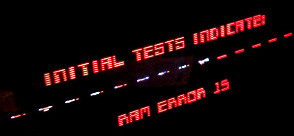
And then the board started throwing up all kinds of RAM errors. The diagnostic tests indicated a RAM error 15, and the 8-seg LED on the ROM board was flashing 1-1-5, which means 1: RAM, Row 1, Chip 5.
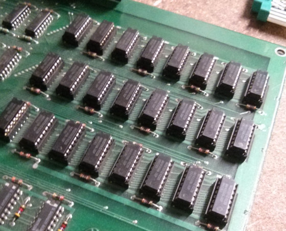
Robotron’s 48 kilo-bytes of RAM
I removed and re-inserted it, but it didn’t help. I swapped it with another chip, and got a bad RAM error again, this time 1-3-1. Same error in a different place? That’s odd, and it’s probably not actually a RAM problem.
Google says a 1-3-1 is indicative of a power issue. If your +5V isn’t reliable, you’ll get RAM failures. I checked, and the 4-pin PC-HDD connector I was using had become a bit loose. So I tightened up the pins a bit, and the board sprang back to life.
4. Bad Audio. Again
And then the sound didn’t work. Or rather, it sort of worked. If you maxed the volume and put the speaker against your ear you could just make out a mosquito playing Robotron sounds somewhere deep inside. Basically, the amplifier wasn’t.
I checked the audio board. Test point 2 was reading -1V. Wait, it’s 1V. No, 2V. 1.5V. WTF is this random voltage shit? What should have been a steady -5V was basically all over the place. I checked my power supply, found that it had a -12V line, and ran a wire directly to TP2 (after removing the fuse that was connecting -5V from the JAMMA harness). And presto, the audio was back.
The problem was the power rectifier, which had apparently decided against a life of awesome on my Robotron PCB. But since its primary job was creating smooth DC power from the original unregulated power supply, I figured I’d be safe to bypass it. The power supply I was using was a fairly modern PC power supply with a regulated 12V output, which shouldn’t require the rectifier anyway.
5. No shooty
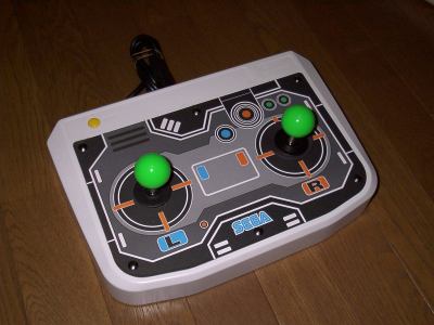
When I had first assembled the JAMMA conversion harness to play Robotron on my more modern gear, I had configured it to use both JAMMA joystick inputs: P1 stick for movement, P2 stick for shooting. This made a lot of sense when I was playing with a Virtua Stick Pro, but less when I was using the modified Virtual On twinstick seen above. So I added four new wires to the JAMMA connector, so that the P2 joystick inputs were also connected to P1 buttons 1-4.
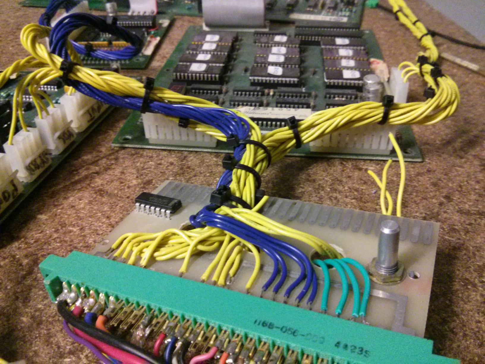
Click for larger view of Jamma adaptor & harness
The green wires are new. Click for different view of harness
6. Bad Joystick
The whole point of this exercise was to play Robotron on what I think are the best joysticks ever made, from Nintendo. These little all-metal joysticks are short, have a small throw, click just the way I like, and have an 8-way gate with an unusual deep indent at each point.
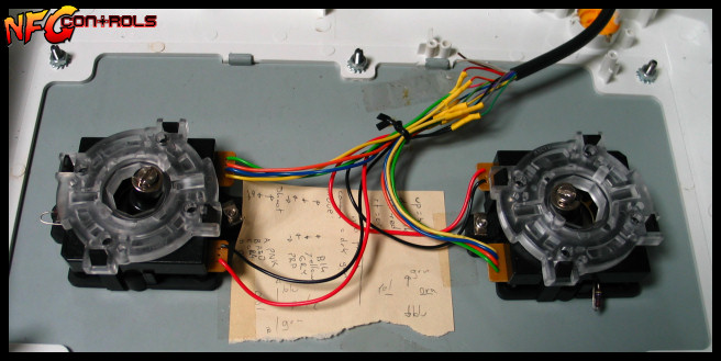
I had just assembled this twin stick, replacing a couple of ASCII optical mechs (shown above – they should have been sublime, but in actuality are large and slow). The Nintendo stick was pretty much the perfect thing in another recent project and so I was excited to play the best game with my favourite sticks.
But what’s this!? This suuuuucks, what’s going on? Movement was perfect, all 8 directions were responsive and easy, but shooting was reluctant and tended to avoid diagonals, making the game nearly unplayable. I was close to despair, bashing harder on the damn thing until I thought to have a look underneath.
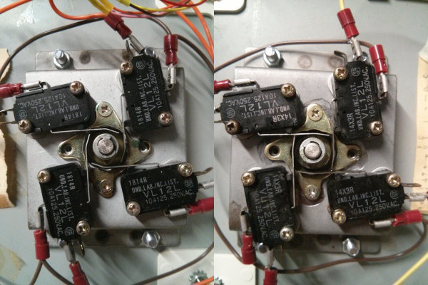
You can clearly see the left stick has bent actuators, so that the stick will easily push both switches in the diagonal position. The one on the right, however, has been straightened out by a previous owner and they would only activate both switches if you pushed them just right. So sometimes I could shoot diagonal, sometimes not.
I took the pliers to them and corrected this hideous malformation, and finally played me some Robotron.
Much to the neighbor’s irritation, no doubt. That little audio amp really pushes out the sound. =D
Further Reading
lomont.org has a techy but very interesting writeup of the Robotron sound algorithms.
sharebrained has an incredibly intricate Robotron Autopsy, breaking down many functions of the arcade board in a clear, step by step fashion. It’s not for the uninitiated, but if you like working shit out, here is much shit with which you can work.
Robotron Guidebook has many interesting documents, including the story of Christian Gingras (Archive link (thanks SC!), the original is dead) who completely reverse-engineered the game back in 1984 and showed Larry DeMar and Eugene Jarvis where they went wrong, to their astonishment.
And Robotron-2084.co.uk has downloadable PDFs of original instructions and schematics for Robotron and other Williams games. And other stuff too.
Also from robotron-2084.co.uk, a great JAMMA conversion PDF which will help you hook up your own Williams boardset to a modern JAMMA rig.
--NFG
[ Jan 15 2014 ]
| Next Post | Navigation | Previous Post |
|---|
Comments
Dave Langley
Jan 20 2014
Great Article.
Thanks for the mention of my website :-)
Pat
Oct 15 2023
Hi, the link to the Christian Gingras story does not work, do you have one that does?
NFG
Nov 25 2023
It looks like it’ll be back eventually. I can’t be more help than that, sorry.
NFG
Aug 2 2024
User SC dropped an Internet Archive link to the missing article. Thanks SC!
Name:
Email:
Website:


RobotronGuide
Jan 20 2014